What Is the Difference Between Knit and Meld Lines and Why Does It Matter?
|
Getting your Trinity Audio player ready...
|
In the plastic injection moulding industry, we work with materials that are byproducts of oil refinement and moulds made of metal casting, so our terminology is bound to be at least slightly confusing.
Three terms that often get mixed up are weld, meld, and knit lines. Meld and knit lines are actually both different types of weld lines. Let’s review what causes meld and knit line imperfections, how they affect part durability, and what the difference between them is.
What Causes Knit and Meld Lines?
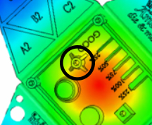
Like many part inconsistencies, these unwanted features are rooted in product design. Since our material is injected through a gate, it must flow through the cavity and around various features, such as holes or bosses (shown in Image 1).
If a knit line is present in a screw boss, the boss will likely crack when a screw is driven into it, leading to part inconsistencies.
For automotive parts, this results in parts that bump, squeak, or rattle.
For electronics, the broken screw boss will not allow proper compression of a seal, causing precious PCB (printed circuit board) to be damaged with water.
For plumbing parts, if these occur in an O-ring groove, there is a possibility that there will be a weeping of fluid, causing a slow drip.
In the pipe fitting industry, if these are not managed well, a fitting will not pass burst or crush testing, yielding product field failures.
Think of this like water flowing down a river with a rock protruding through the surface. Once the water hits the rock, the flow must split, continue around, and converge on the opposite side.
What we want to focus on is the converging to determine if it’s a knit or meld line.
Meld Line
A meld line is defined as the remerging of two flow fronts after the plastic flow has been split by a feature within the part design. Visualize this as you’re getting onto the motorway after a long day at the office—we are all going the same direction and have to figure out how to get there without damage. In image 2, we can see how the flow front splits due to the rectangular core out and merges again on the opposite side. Since there is more space inside the mould cavity, the flow front continues onward, creating a new flow front.
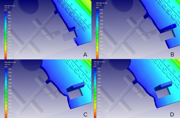
This joint is not as strong as an uninterrupted flow. Since the flow front can merge together and continue flowing through the cavity, there is a greater chance of being able to pressurize this area, therefore increasing its strength.
Knit Line
A knit line is when two flow fronts come together but, rather than merging, it’s like a head-on collision at a 4-way junction. This isn’t pretty and will not end well.
Once these two flow fronts meet, there is no more cavity geometry to flow through, thus making it difficult to pressurize this area of the part. Subsequently, the result is even weaker than a meld line.
Material Selection
Certain materials are more forgiving with strength than others. Materials (HDPE, PP, POM) with streamlined structure (shown in Image 4) typically yield higher strengths because the polymer chains can more easily intermingle. The random structures that contain benzene rings found in other materials (PC, PMMA, ABS) reduce the ability for the polymer chains to easily merge together. These benzene rings also increase viscosity, reduce shrink rate, and increase strength; the notable exception being knit and meld lines.
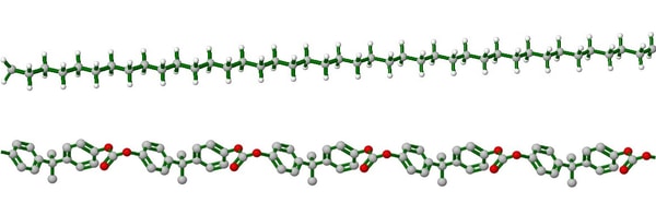
Bottom, PC with random structure
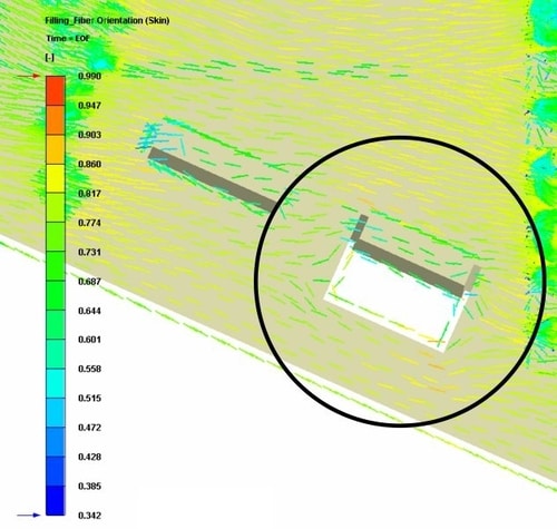
Materials that have physical fillers like glass, carbon, metal flakes, etc. reduce the ability to positively influence the strength of a knit or meld line. This occurs for several reasons.
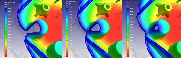
First, the temperatures in which we process most thermoplastics (200 to 315o C) are drastically below the melting point of those types of fillers (glass is 1400 to 1600o C) … if they even melt. In this situation, not only do we have a feature inside the cavity impeding the plastics flow, but we have a solid suspended in the flow front, further wreaking havoc. Therefore, we need to review the fiber orientation prior to the feature and how it differs after the feature (shown in Image 5).
The key to understanding changes in strength within a part that has been compromised is understanding how test samples are broken down and how the data is collected.
The Izod Impact test, shown below in Image 6, uses a weighted pendulum to strike a sample. Readouts are provided in the amount of energy required to break the sample, typically in ft-lb/in2. The more energy required to break the sample, the stronger the material is.

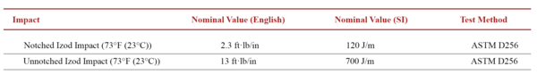
Another area that we need to review is the ASTM data from the notched and unnotched samples, shown below in Image 7. Due to the elements that create the polymer, their arrangements and bonds determine how much strength is retained. A knit line is similar to that of a notch found in the ASTM sample.

Though a moulded part with a knit line may not behave exactly like the test sample, the datasheet will show us how much strength could be potentially lost.
As an example, there are certain materials that are so strong, the ASTM test cannot break the unnotched sample, but the value of the notched sample is tremendously low. One example of this is PC used in the medical industry (shown below in Chart 1).

Other materials, like PP shown below in Chart 2, are breakable at the ASTM test method when both notched and unnotched.
Neither of these materials are bad, but we must understand their limitations and how to properly accommodate the design to achieve the desired objective.
What we look at for indications of strength is the falloff between the unnotched and notched sample. This can help us understand how weak a knit line could potentially be compared to an uninterrupted flow of plastic.
Mould Design
Where a knit or meld line will be within the part geometry is heavily influenced by the gate location. Through the use of flow simulations, we can predict where those may occur. However, gate locations may be selected based on part functionality, placing knit or meld lines in critical areas for proper functionality.
Processing
Improving the strength of knit or meld lines can be tremendously difficult with processing, since there are so many factors that are already locked in, such as part geometry, gate location, flow length, and material. The best we can hope for is to increase pressurization of the knit or meld line through the combination of melt temperature, mould temperature, flow rates, and holding pressures.
Conclusion
The difference between a knit and meld line is significant, dramatically impacting the part’s structural integrity. Knit and Meld lines are inherent to plastic injection moulding. Eliminating them is often difficult due to product requirements. However, with a collaborative effort between product designer, mould maker, and moulder, success is certainly obtainable.
Click here to read the original article on the RJG website.

RJG Technologies
+44 (0)1733 232211
Website
Email