Using Plastics Simulation to Overcome a Fear of Fibres
|
Getting your Trinity Audio player ready...
|
A sure-fire way to make any injection mould toolmaker or processing engineer uneasy is to utter the words “fibre reinforced”; and not without good reason.
Fibre reinforced polymer materials have seen a constant increase in uptake across all industries. Their benefits are substantial; with the fibres providing superior strength, stiffness and creep resistance over conventional unfilled polymers. These outstanding properties make these materials attractive alternatives to metal in many applications.
All this is fantastic news for product designers, but achieving exacting dimensional tolerances can be a real headache for those responsible for manufacturing these components.
At the root of the problem is shrinkage. All thermoplastics shrink during manufacture and this shrinkage is compensated for by making the mould tool slightly larger than the desired part. The fibres distributed within the polymer matrix resist this shrinkage, but the extent of this effect depends on the fibre direction.
During filling the fibres are aligned by the shear forces within the melt flow, which tend to align fibres in the flow direction. The sample plaque below shows a typical fibre orientation, resulting in low shrinkage in the flow direction.

The problem is exaggerated for materials with very high fibre filler content. It’s not unusual to see transverse shrinkage 5-10x higher than parallel.
Take this clam shell handle from a garden tool as an example. A 33% glass fibre reinforced nylon material was specified by the designer to ensure sufficient strength and stiffness. When the first parts came off the injection moulding machine there were complaints of poor fit when assembled.
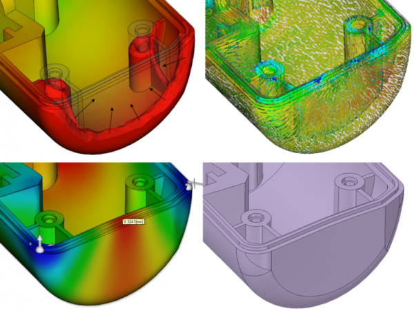
By running a quick Autodesk Moldflow analysis on the part the cause of the problem becomes clear. As the polymer reaches the end of the part the flow front converges on the end face. The resulting radial alignment of the fibres causes a high spot on the mating face.
In Moldflow, the warped shape can now be exported as a modified CAD geometry file. Then it’s just a case of dropping the warped model back into the CAD assembly to assess fit and function..


Many distortion issues can be mitigated by careful control of the moulding process but distortion due to fibre orientation effects is often the exception. Gate position is single biggest factor in achieving good part quality. For the handle component Moldflow analysis shows us that gating close to the end face minimises the distortion issues.
By taking the CAD model into a visualisation package like Keyshot or Autodesk Showcase it’s easy to assess the improvement.
To learn more about identifying and solving issues like this, our Introduction to Design For Injection Moulding course is a great place to start.
Also feel free to contact me or one of our other plastics specialists for advice on a new project or for a quick demonstration on how to use Moldflow for modelling fibres.
Louis Barnes, Principal Engineer, Wilde Analysis Ltd
![]()
Wilde Analysis
+44 (0) 161 474 6886
Website
Email