
Design Decisions That Set Your Injection Mould Cost // Alliance Tooling Blog
 George Nowill
- 6 minutes read

|
Getting your Trinity Audio player ready...
|
By the time a part drawing reaches a toolmaker, most of the mould’s cost has already been decided, according to Alliance Tooling. Wall sections, draft, undercuts, tolerances and cosmetic requirements set how complex the tool must be, how long each cycle takes, and how much maintenance the mould will need over its life.
A toolmaker can work around a difficult design, but every workaround costs something: extra mechanisms, more machining time, longer cycles or a higher scrap rate. The cheapest changes are the ones made while the part is still on screen.
Below are the five design decisions Alliance Tooling sees driving tool cost most often, what each one does to the mould, and what to consider before you send a drawing out for quotation.
1. Wall Thickness
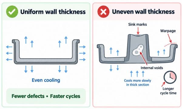
Uniform walls are the single most effective way to keep cycle time and defect rates down. Plastic shrinks as it cools, and thick sections cool more slowly than thin ones, so uneven walls cool unevenly.
The result is usually one or more of the following:
- Sink marks where a thick section pulls the surface inwards as it shrinks
- Warpage where different areas of the part shrink by different amounts
- Internal voids inside thick sections that can weaken the part without being visible
- Longer cycle times, because the part can only be ejected once its thickest section is solid enough. Cooling time rises steeply with wall thickness, so one heavy boss can set the pace for the whole part.
What to consider: core out thick areas rather than leaving them solid, use ribs for stiffness instead of extra thickness, and blend transitions between thick and thin sections gradually. Suitable wall thicknesses vary by material, so check the resin supplier’s design guidance for the grade you intend to use.
2. Draft Angles
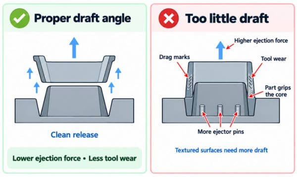
Draft is the slight taper on faces parallel to the mould’s opening direction, and it lets the part release cleanly. Without it, the part grips the core as it shrinks and drags along the steel during ejection.
Too little draft typically causes drag marks on the part, higher ejection forces, more ejector pins, and faster wear on the tool surfaces. In some cases it forces a more complex ejection system than the part would otherwise need.
What to consider: add draft to every face in the line of draw unless there is a functional reason not to. Even a degree or so makes a real difference. Textured surfaces need noticeably more draft than polished ones, and the deeper the texture, the more draft it needs. Agree surface finishes before the design is fixed rather than adding texture later, because retrofitting draft to a finished design can ripple through mating parts.
3. Undercuts
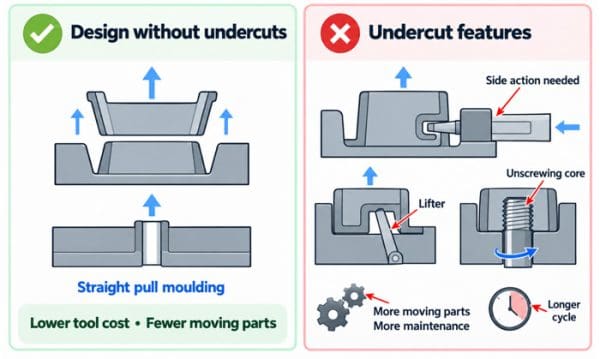
An undercut is any feature that stops the part from being pulled straight out of the mould, such as a side hole, an internal clip or an external thread. Each one needs a mechanism to release it.
The usual options are side actions (sliding cores driven by angled pins or hydraulics), lifters that move sideways as the part is ejected, and collapsible or unscrewing cores for internal features and threads. Every one of these adds machining time and cost to the tool. They also add moving parts that need maintenance, can wear or seize, and may extend the cycle.
What to consider: question whether each undercut is essential. Common alternatives include:
- Pass-through cores, where an opening in the part allows a feature to be formed by the two mould halves meeting, with no moving parts
- Relocating holes so they sit in the line of draw
- Reworking clips and snap fits so they can be moulded without side actions
- Secondary operations, such as drilling a hole after moulding, which can be cheaper at low volumes than adding an action to the tool
The right answer depends on volumes and the part’s function, which is why it is worth discussing with the toolmaker before the design is frozen.
4. Tolerances
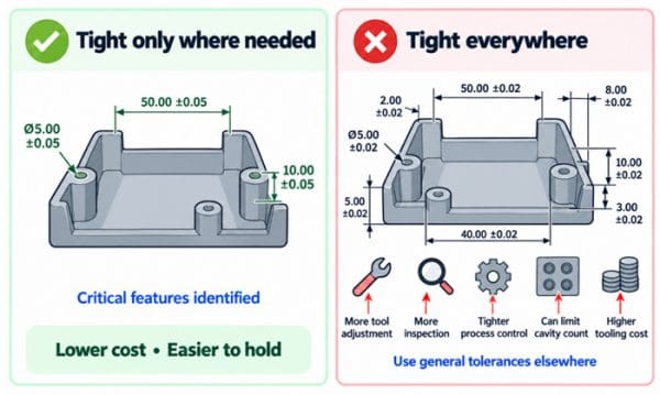
Tight tolerances applied across a whole part are one of the most common avoidable costs in tooling. Plastics shrink, and shrinkage varies with material, wall thickness, flow direction and processing conditions, so very tight limits are harder to hold than they would be in machined metal.
Holding a tight tolerance can mean more precise tool machining, more trial-and-adjustment rounds during sampling, tighter process control in production, and more inspection. Sometimes it also limits the number of cavities, because each extra cavity adds variation.
What to consider: apply tight tolerances only to features that need them, such as mating faces, sealing surfaces and locating features, and use general tolerances elsewhere. Identifying the critical dimensions clearly on the drawing tells the toolmaker where precision matters and where there is room to optimise. Recognised standards for moulded part tolerances, such as ISO 20457, are a useful reference for what is realistically achievable.
5. Gate Location and Cosmetic Surfaces
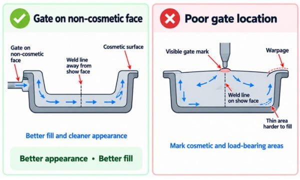
The gate is where molten plastic enters the cavity, and its position affects how the part fills, how it shrinks and how it looks. It is also one of the decisions designers most often leave entirely to the toolmaker, without telling them what matters.
Gate location influences where weld lines form (where two flow fronts meet, which can be visibly marked and weaker), whether thin areas fill fully, how much the part warps, and where the gate vestige ends up. A gate placed purely for appearance can compromise filling, and a gate placed purely for filling can leave a mark on a show face.
What to consider: mark which surfaces are cosmetic and which are not, and say where a gate mark or weld line would be unacceptable. Flag any area that carries load, because a weld line there may matter structurally. Given that information, the toolmaker can propose a gate position that balances filling, strength and appearance, and can use mould flow analysis to check it before steel is cut.
Bring the Toolmaker in Early
A design for manufacture (DFM) review before the design is frozen is the simplest way to catch these issues while they are still cheap to change. It does not need a finished design, just enough information for the toolmaker to see how the part will be made.
A useful DFM review pack includes:
- 3D CAD model (STEP is the most widely accepted format) and any 2D drawings
- Material, or a shortlist if it is not yet decided
- Expected annual volumes and product life, which drive decisions on cavitation, tool steel and whether a mechanism is worth the cost
- Critical dimensions and tolerances, clearly identified
- Cosmetic requirements, including which faces are show surfaces and any texture or finish
- Assembly context, meaning what the part mates with and how
The output should be a clear list of suggested changes, with the reason for each and its effect on tooling and part cost, so your design team can decide which ones are worth making.
Read more news from Alliance Tooling here.

Alliance Tooling
+44(0)116 275 0584
Website
Email